
Die Auswahl der richtigen schrägen Spiralfeder erfordert ein Verständnis von Lasttyp, Material, Beschichtung und Rillendesign. Dieser umfassende Leitfaden führt Ingenieure durch die wichtigsten Parameter, um eine optimale Leistung bei Dichtungs-, EMI-Abschirmungs- und leitfähigen Anwendungen zu gewährleisten.
Kantige Schraubenfedern-auch bekannt als schräge Schraubenfedern- gehören zu den vielseitigsten mechanischen Komponenten, die in der modernen Technik verwendet werden. Ihre einzigartige Geometrie ermöglicht es ihnen, eine gleichmäßige Kraft über einen großen Auslenkungsbereich zu erzeugen, was sie ideal für Anwendungen macht, die von Hochleistungsdichtungen bis zu kritischen EMI-Abschirmungen und elektrischen Verbindungen reichen.
Die Auswahl der richtigen geneigten Schraubenfeder für eine bestimmte Anwendung erfordert jedoch mehr als nur die Übereinstimmung mit einer Teilenummer. Ingenieure müssen die Art der Belastung, die Kraftklassifizierung, das Material, die Beschichtung, die Rillenform und die Umweltfaktoren berücksichtigen. Dieser Leitfaden bietet einen systematischen Ansatz, um die richtige Wahl zu treffen.
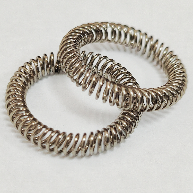
Eine schräge Schraubenfeder ist eine Präzisionsfeder, bei der die einzelnen Windungen in einem Winkel geneigt (gekippt) relativ zur Mittellinie der Feder. Diese Verkantung bewirkt ein einzigartiges mechanisches Verhalten: Beim Zusammendrücken rollen die Windungen, anstatt sich einfach durchzubiegen, was zur Folge hat:
Aufgrund dieser Eigenschaften sind Schraubenfedern mit schrägem Querschnitt in drei Hauptanwendungen besonders wertvoll:
| Anmeldung | Funktion |
|---|---|
| Federkraftbetätigte Dichtungen | Sorgt für eine kontinuierliche Dichtkraft gegen die Dichtlippe |
| EMI/RFI-abschirmende Dichtungen | Bietet leitenden Kontakt zwischen Gehäuse und Tür/Rahmen |
| Elektrische Anschlüsse | Sorgt für einen widerstandsarmen Kontakt in Steckern und Batteriekontakten |
Die erste Entscheidung bei der Auswahl einer geneigten Schraubenfeder ist die Bestimmung der Richtung der Krafteinleitung. Geneigte Schraubenfedern können für zwei Hauptlastarten konfiguriert werden:
Bei radialer Belastung wird die Feder zusammengedrückt senkrecht zu seiner Mittellinie. Diese Konfiguration wird verwendet, wenn die Feder in einer Nut auf einem Kolben oder einer Welle installiert ist, wobei die gegenüberliegende Fläche (Gehäuse oder Bohrung) die Feder radial zusammendrückt.
Typische Anwendungen:
Bei axialer Belastung wird die Feder zusammengedrückt parallel zu seiner Mittellinie. Die Feder wird in der Regel in eine Stirnnut eingebaut, wobei ein Gegenflansch oder ein Deckel sie axial zusammendrückt.
Typische Anwendungen:
Wichtigster Punkt: Nicht alle schrägen Schraubenfedern sind für beide Belastungsarten geeignet. Die Hersteller bieten in der Regel spezielle Federausführungen an, die entweder für radiale oder axiale Belastung optimiert sind. Die Angabe der richtigen Belastungsart ist entscheidend für das Erreichen der beabsichtigten Leistung.
Kantige Schraubenfedern sind in mehreren Kraftklassen erhältlich, so dass die Konstrukteure die Druckkraft der Feder an die Anforderungen der Anwendung anpassen können. Die drei Standard-Kraftklassifizierungen sind:
| Klasse Kraft | Ungefährer Kraftbereich | Typische Anwendungen |
|---|---|---|
| Geringe Kraft | ~1,5 lb pro linearem Zoll | Kunststoffgehäuse, reibungsarme Dichtungen, leichte Baugruppen, empfindliche Elektronik |
| Mäßige Kraft | ~10 lb pro linearem Zoll | Allgemeine industrielle Abdichtung, Standard-EMI-Abschirmung, Anschlüsse für mittlere Lasten |
| Standard Kraft | ~30 lb pro linearem Zoll | Hochdruckdichtungen, hochzuverlässige EMI-Abschirmung, Luft- und Raumfahrt, Militär |
Bei der Auswahl der geeigneten Kraftklasse müssen mehrere Faktoren berücksichtigt werden:
Praktischer Ansatz: Beginnen Sie im Zweifelsfall mit der mittleren Kraftklasse - sie bietet einen ausgewogenen Ausgangspunkt für die meisten Anwendungen. Passen Sie sie je nach den spezifischen Anforderungen nach oben oder unten an.
Die Wahl des Materials beeinflusst die mechanischen Eigenschaften, die Korrosionsbeständigkeit, den Temperaturbereich und die Leitfähigkeit der Feder. Gängige Werkstoffe für geneigte Schraubenfedern sind:
| Material | Wichtige Eigenschaften | Geeignete Umgebungen |
|---|---|---|
| Rostfreier Stahl 302/304 | Gute Korrosionsbeständigkeit, mittlere Festigkeit, kostengünstig | Allgemeine Industrieanwendungen, moderate Temperaturen, nicht kritische Anwendungen |
| Rostfreier Stahl 316 | Hervorragende Korrosionsbeständigkeit, insbesondere gegen Chloride | Meeresumwelt, medizinische Geräte, chemische Belastung |
| Beryllium-Kupfer (BeCu) | Ausgezeichnete Leitfähigkeit, gute Federeigenschaften, nicht magnetisch | EMI-Abschirmung, elektrische Kontakte, niederohmige Verbindungen |
| Hastelloy / Inconel | Hervorragende Korrosionsbeständigkeit, Hochtemperaturfähigkeit | Triebwerke für die Luft- und Raumfahrt, Öl und Gas im Bohrloch, chemische Verarbeitung |
| Elgiloy | Hohe Festigkeit, hervorragende Ermüdungsfestigkeit, korrosionsbeständig | Medizinische Implantate, Luft- und Raumfahrt, hochzyklische Anwendungen |
Optionen für die Beschichtung die Leistung weiter verbessern:
Die richtige Gestaltung der Rillen ist für das Erreichen der beabsichtigten Kompression und Kraft entscheidend. Die Nut muss so bemessen sein, dass sie die Feder aufnimmt und gleichzeitig eine korrekte Kompression gewährleistet.
| Parameter | Definition | Bedeutung |
|---|---|---|
| Tiefe der Rille | Abstand von der Montagefläche bis zum Nutengrund | Bestimmt den Prozentsatz der Kompression; zu tief reduziert die Kraft; zu flach überkomprimiert |
| Rillenbreite | Seitlicher Raum für den Einbau der Feder | Muss den Sitz der Feder ohne Bindung ermöglichen; normalerweise 10-20% breiter als die Federhöhe |
| Rille Bodenausführung | Oberflächenrauhigkeit des Rillengrundes | Eine glatte Oberfläche verhindert Verschleiß; eine zu glatte Oberfläche kann die Reibung verringern und Federbewegungen verursachen. |
Die Kompression wird als Prozentsatz der freien Höhe der Feder ausgedrückt:
Kompression (%) = (freie Höhe - installierte Höhe) / freie Höhe × 100
Empfohlene Kompressionsbereiche:
Kritische Anmerkung: Ein Überschreiten der empfohlenen Kompression beschleunigt die Spannungsrelaxation und verringert die Lebensdauer der Feder. Eine unzureichende Kompression führt zu einer schlechten Kontaktkraft und beeinträchtigt die Leistung.
Die Betriebsumgebung bestimmt das Material, die Beschichtung und möglicherweise spezielle Beschichtungen.
Um sicherzustellen, dass die ausgewählte Feder die Anforderungen der Anwendung erfüllt, sollten Sie die folgenden Tests anfordern oder durchführen:
A Kraft-Weg-Kurve prüft, ob die Kraft der Feder bei der vorgesehenen Kompression innerhalb der Spezifikationen liegt. Dies ist der wichtigste Test, um die Leistung zu bestätigen.
| Messung | Zweck |
|---|---|
| Kraft bei installierter Kompression | Bestätigt eine ausreichende Kontaktkraft für die Abdichtung oder Leitfähigkeit |
| Krafterhaltung nach Alterung | Validierung der Langzeitstabilität unter Temperatur- und Umweltbelastung |
| Druckverformungsrest | Misst dauerhafte Verformung nach längerer Kompression |
Das folgende Flussdiagramm fasst die wichtigsten Entscheidungspunkte bei der Auswahl einer kantigen Schraubenfeder zusammen:
Text
Beginnen Sie: Identifizieren Sie den Anwendungstyp
        │
        ▼
    Wird die Feder zur Abdichtung, EMI-Abschirmung oder zur elektrischen Verbindung verwendet?
        │
        ▼
Bestimmen Sie die Belastungsart: Radial oder Axial?
        │
        ▼
Kraftklasse wählen: Niedrig, mäßig oder Standard?
        │
        ▼
Wählen Sie Material und Beschichtung entsprechend den Anforderungen an Umgebung, Temperatur und Leitfähigkeit
        │
        ▼
Definieren Sie die Rillenabmessungen, um die 20-30%-Kompression zu erreichen
        │
        ▼
Überprüfen mit Kraft-Durchbiegungsprüfung
        │
        ▼
Auswahl abschließen
Eine übermäßige Kompression - sei es durch zu flache Rillen oder eine falsche Federauswahl - führt zu einem beschleunigten Kraftabbau. Mit der Zeit verliert die Feder an Kontaktkraft, was die Dichtungs- oder Abschirmungsleistung beeinträchtigt.
Nicht alle kantigen Schraubenfedern bieten die gleiche Kraft. Die Verwendung einer Feder mit geringer Kraft, wo eine Feder mit mittlerer Kraft erforderlich ist, führt zu einem unzureichenden Kontakt. Umgekehrt kann eine Feder mit normaler Kraft in einem Kunststoffgehäuse zu Verformungen führen.
Die Standardverzinnung eignet sich gut für saubere, trockene Umgebungen, oxidiert jedoch in feuchten Umgebungen. Für Anwendungen, die Feuchtigkeit oder Salznebel ausgesetzt sind, empfehlen wir Nickel, Gold oder entsprechend beschichtetes Berylliumkupfer.
Die Konstruktionen von Schraubenfedern mit kantigem Querschnitt unterscheiden sich von Hersteller zu Hersteller erheblich. Beziehen Sie sich immer auf die Spezifikationen des Herstellers für Kraft-Weg-Daten, Rillenempfehlungen und Umweltgrenzen.
Überlagerungstoleranzen können dazu führen, dass die tatsächliche Kompression von der beabsichtigten abweicht. Ziehen Sie eine Worst-Case-Toleranzanalyse in Betracht, um sicherzustellen, dass die Feder unter allen Bedingungen innerhalb des empfohlenen Kompressionsbereichs bleibt.
Die Auswahl des richtigen Schrägzugfeder erfordert einen methodischen Ansatz, der die Art der Belastung, die Kraftklassifizierung, das Material, die Beschichtung, die Rillenform und die Umgebungsbedingungen berücksichtigt. Jeder Parameter steht in Wechselwirkung mit den anderen - eine Feder mit hoher Kraft in einem Kunststoffgehäuse kann Schäden verursachen, während eine Feder mit geringer Kraft in einer korrosiven Umgebung vorzeitig an Leitfähigkeit verlieren kann.
Anhand des in diesem Leitfaden beschriebenen Auswahlrahmens können Ingenieure sicher sein, dass sie sich für geneigte Spiralfedern entscheiden, die eine zuverlässige, langfristige Leistung bei Dichtungs-, EMI-Abschirmungs- und elektrischen Verbindungsanwendungen bieten.
Im Zweifelsfall konsultieren Sie die Spezifikationen des Herstellers, fordern Sie Kraft-Durchbiegungsdaten an und validieren Sie diese durch Tests unter realen Bedingungen. Der zusätzliche Aufwand bei der Auswahl stellt sicher, dass das Endprodukt wie vorgesehen funktioniert - beständig und zuverlässig.