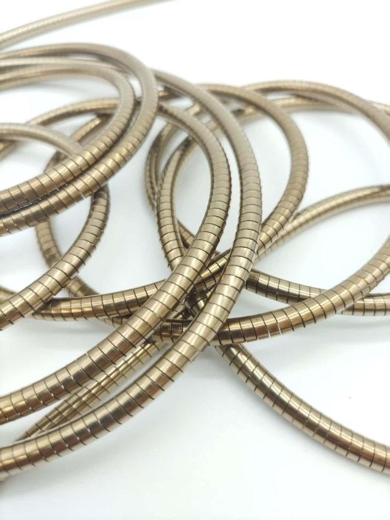
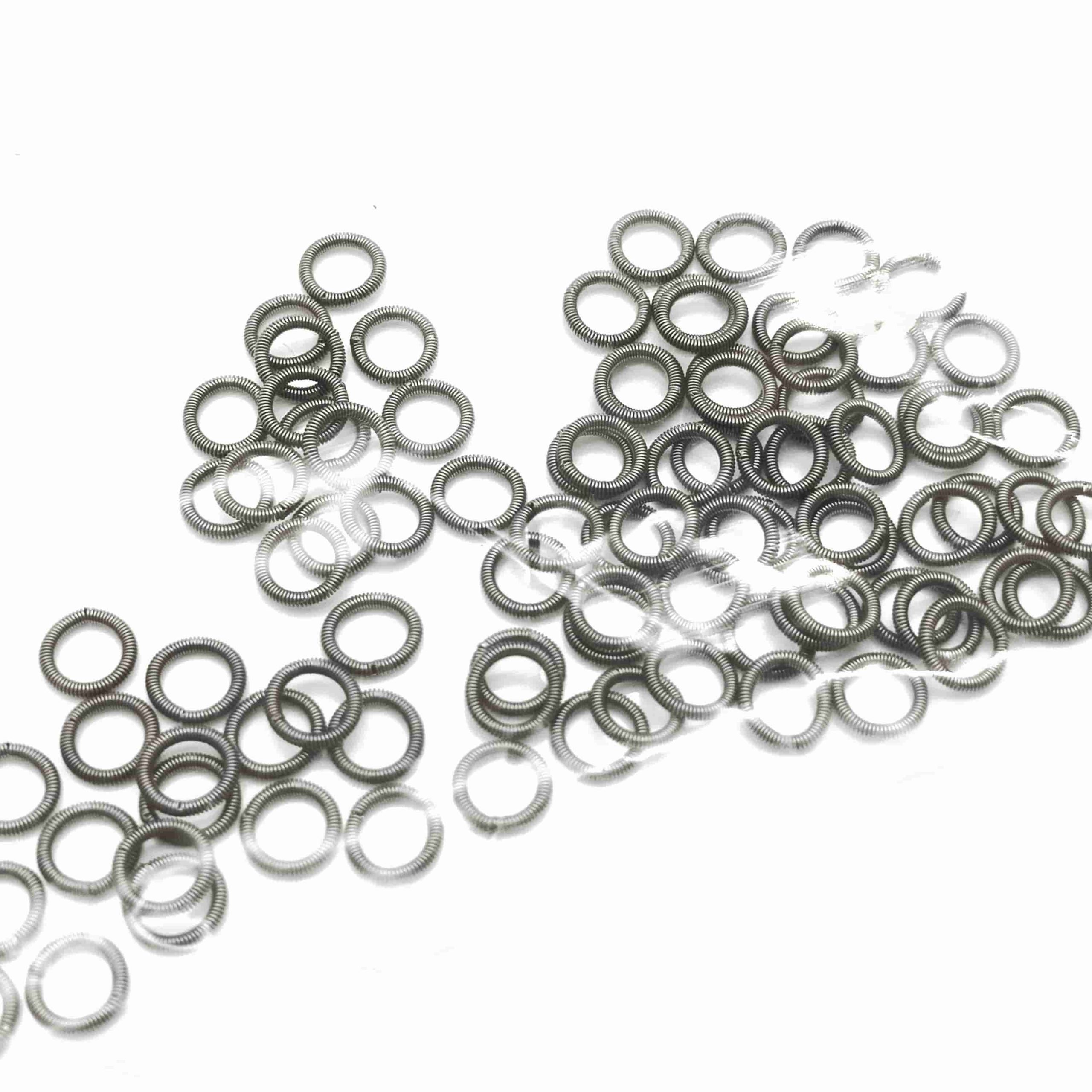
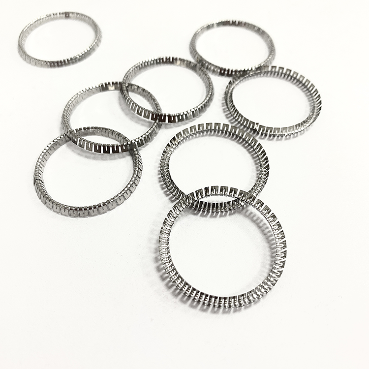
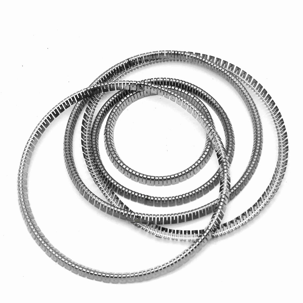
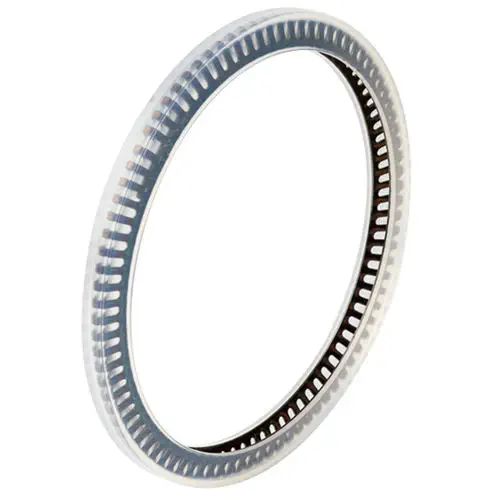
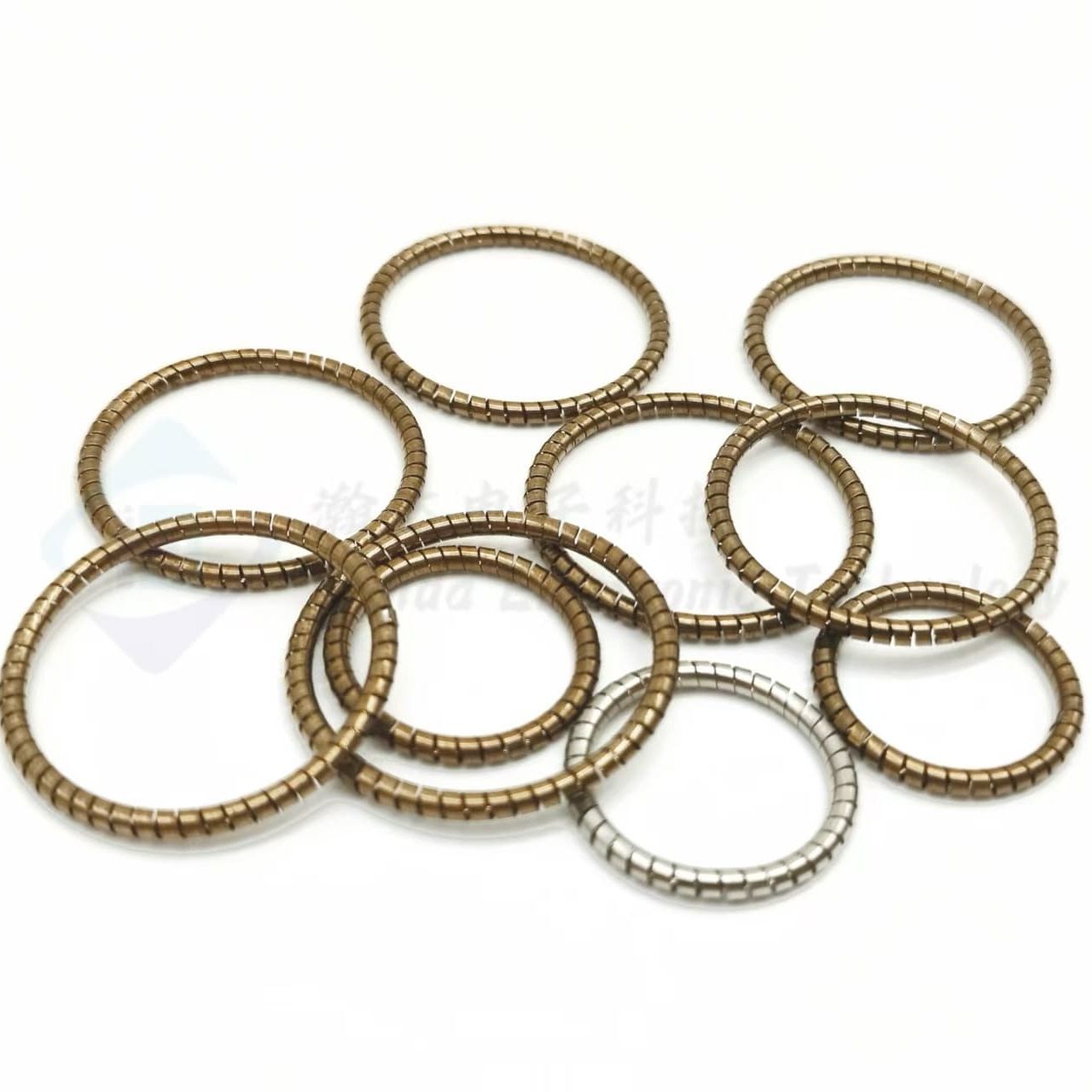
Product Description – Canted Coil Spring for High-Pressure Valve Sealing
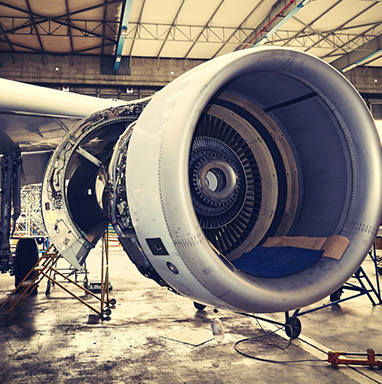
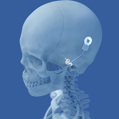
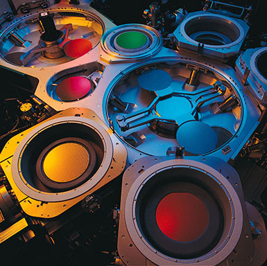
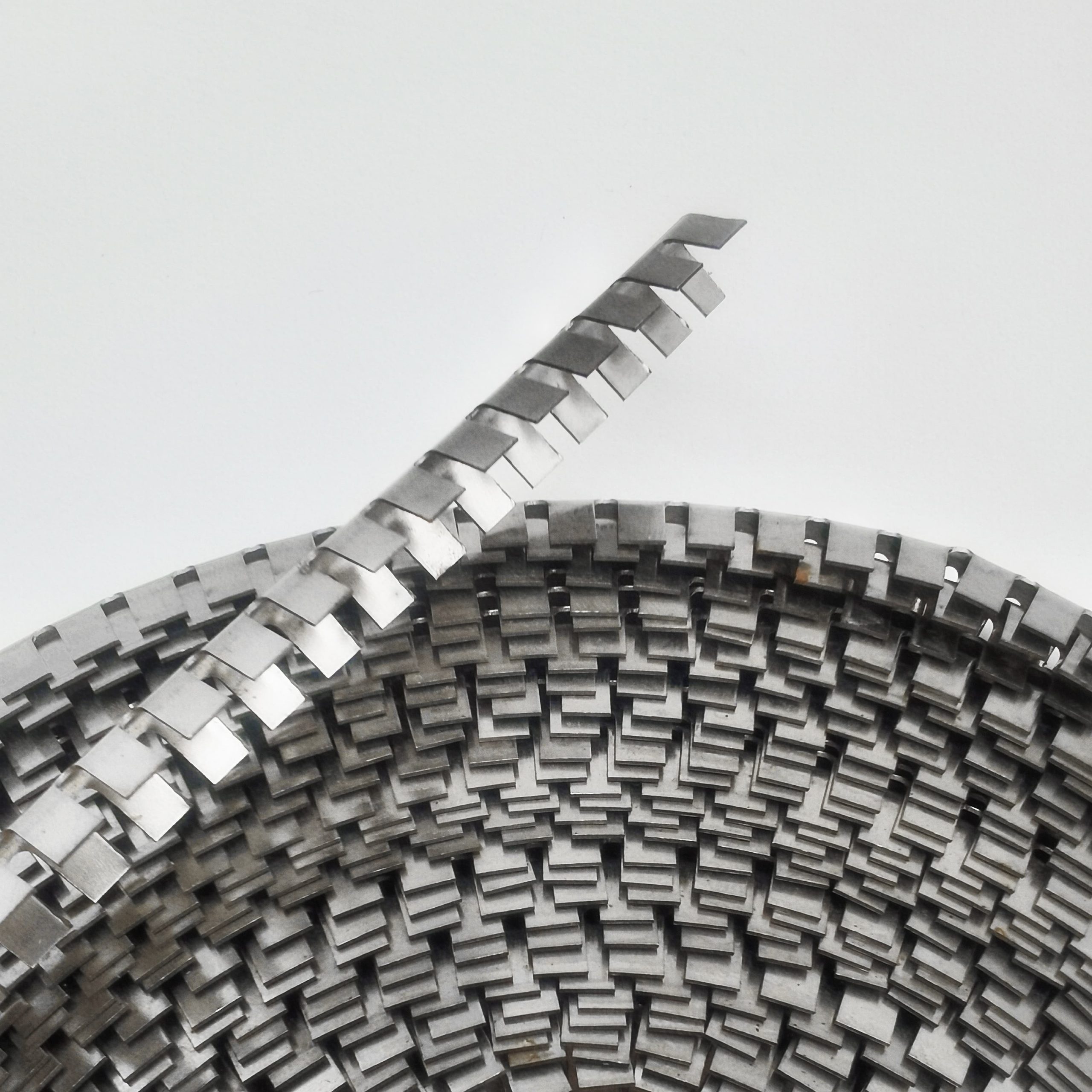
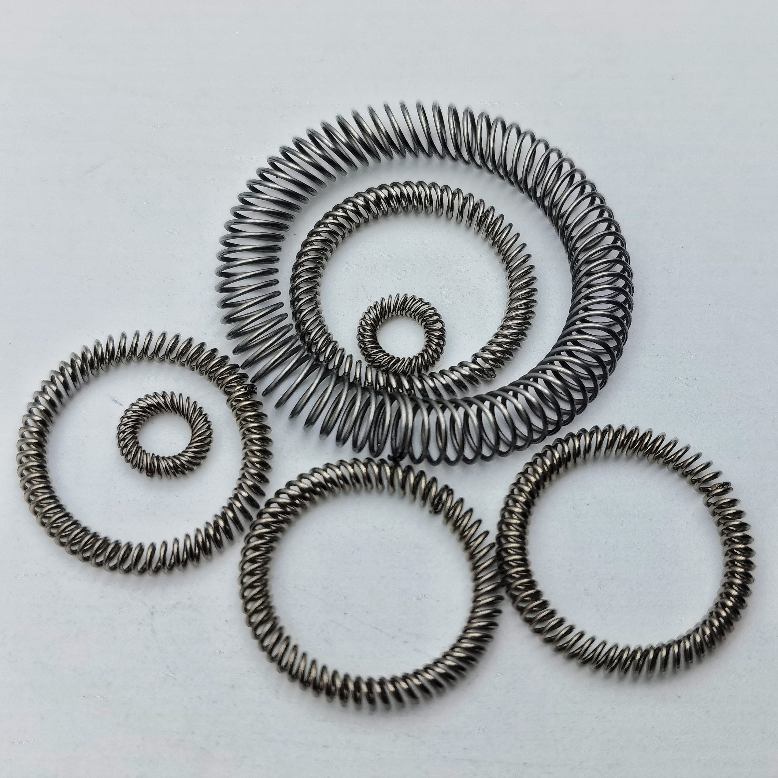
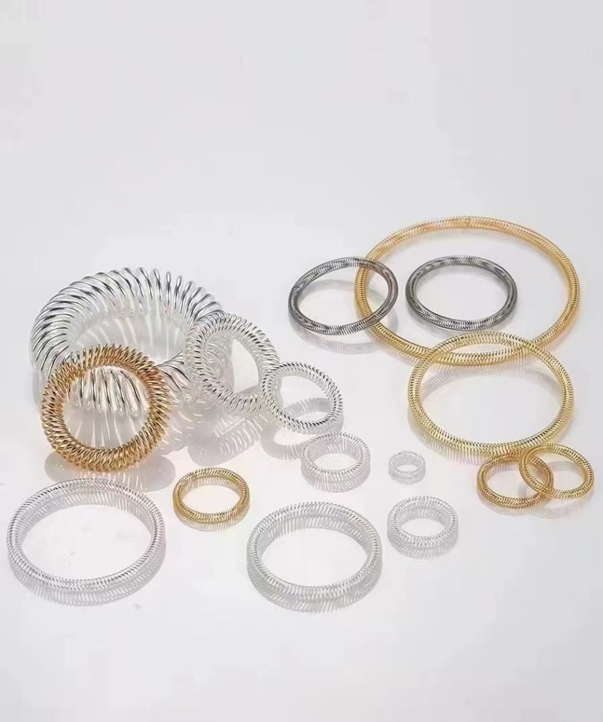
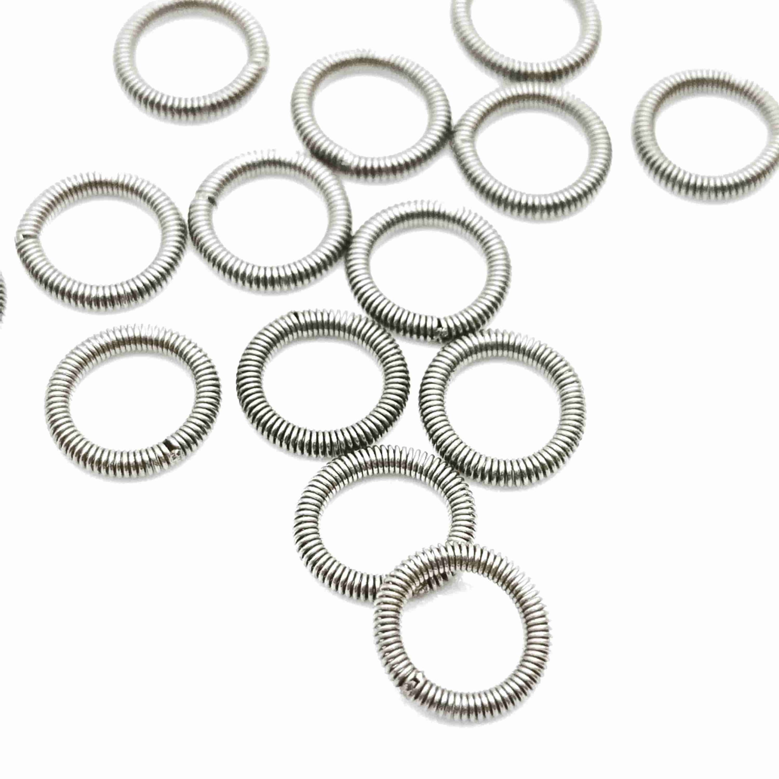
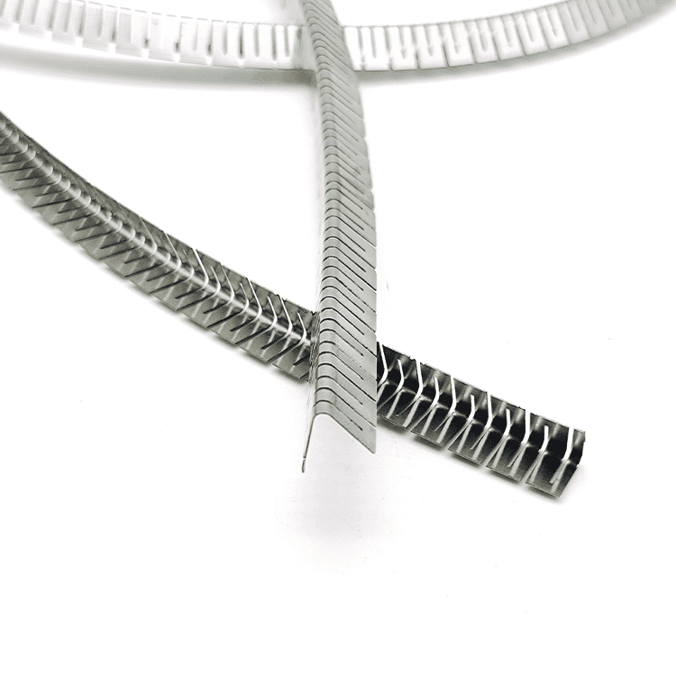
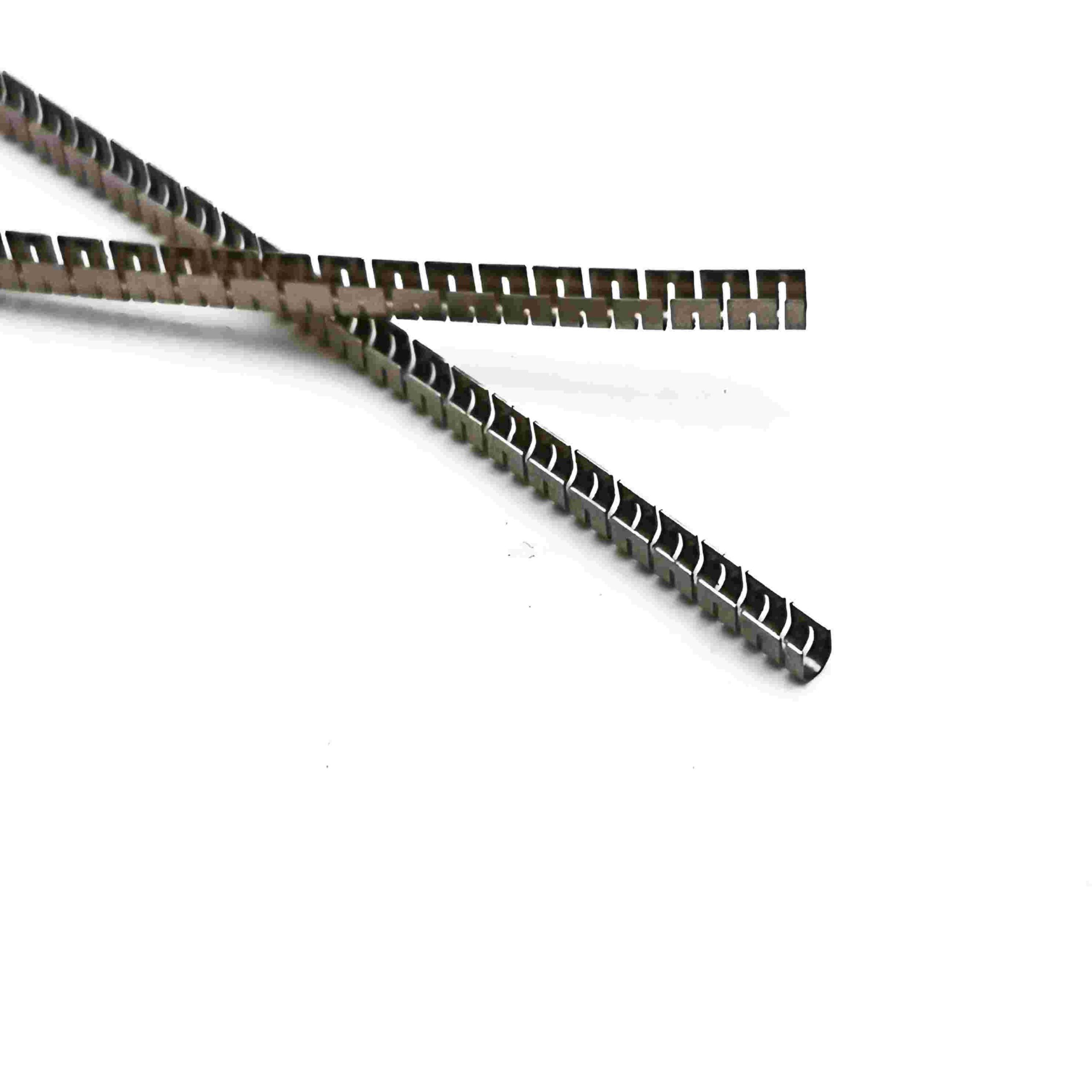
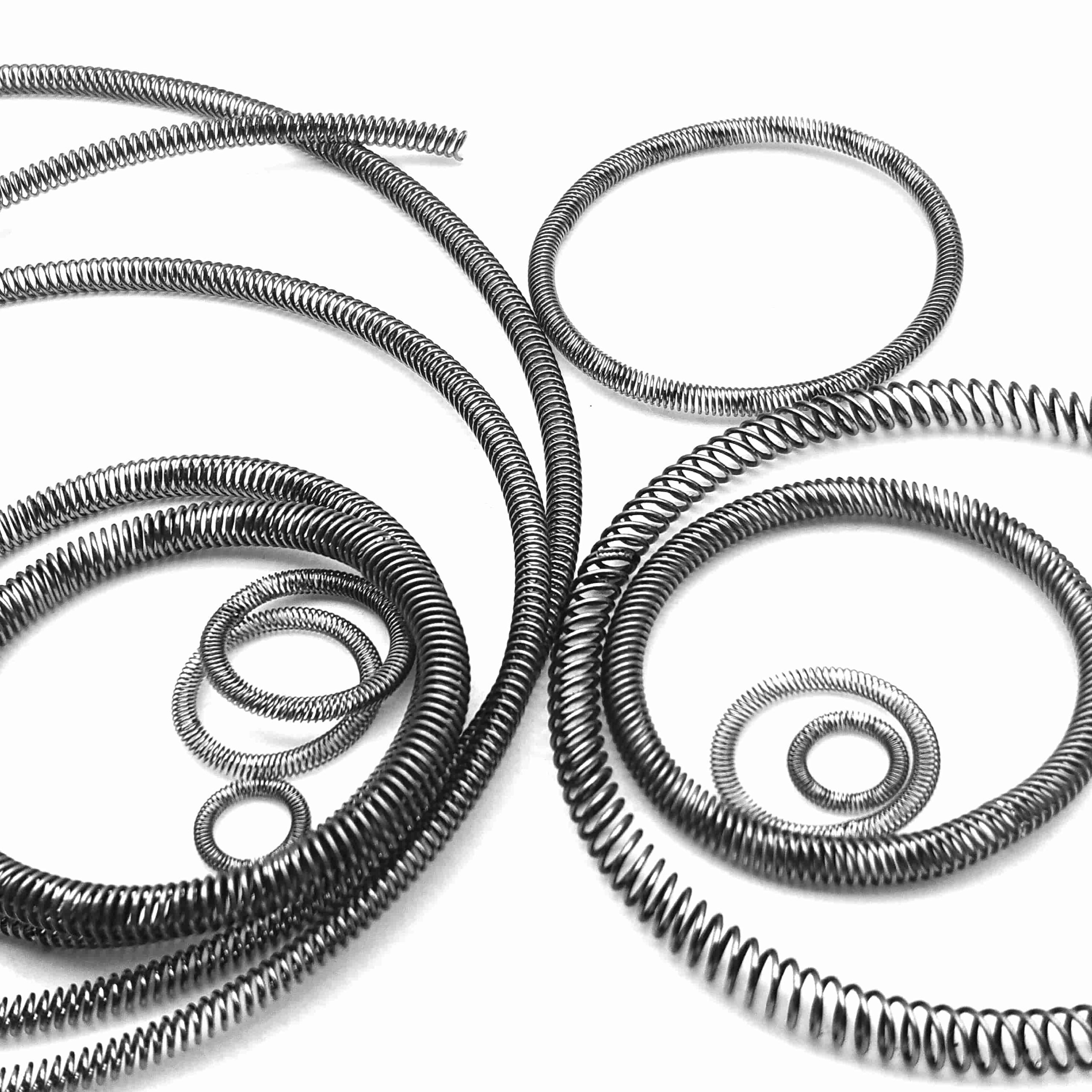
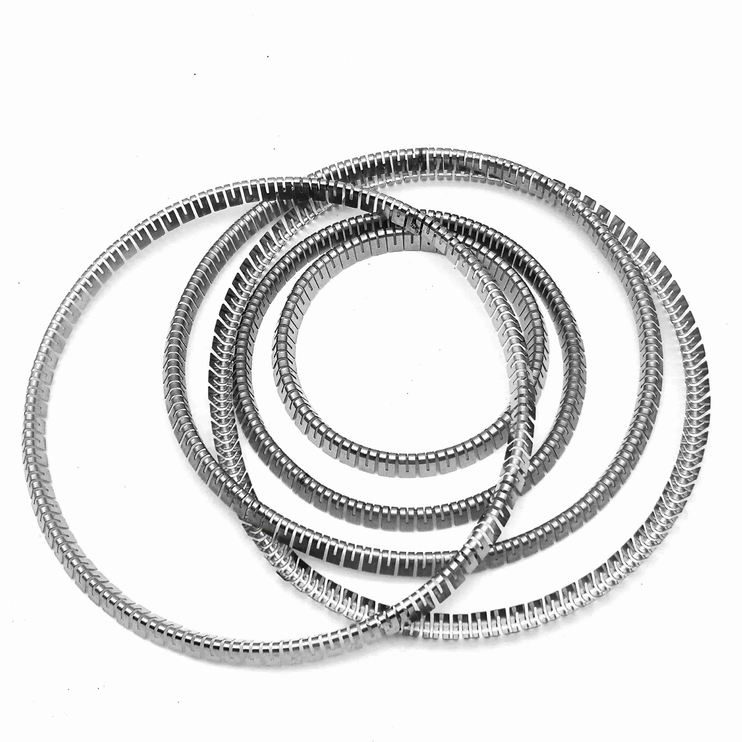
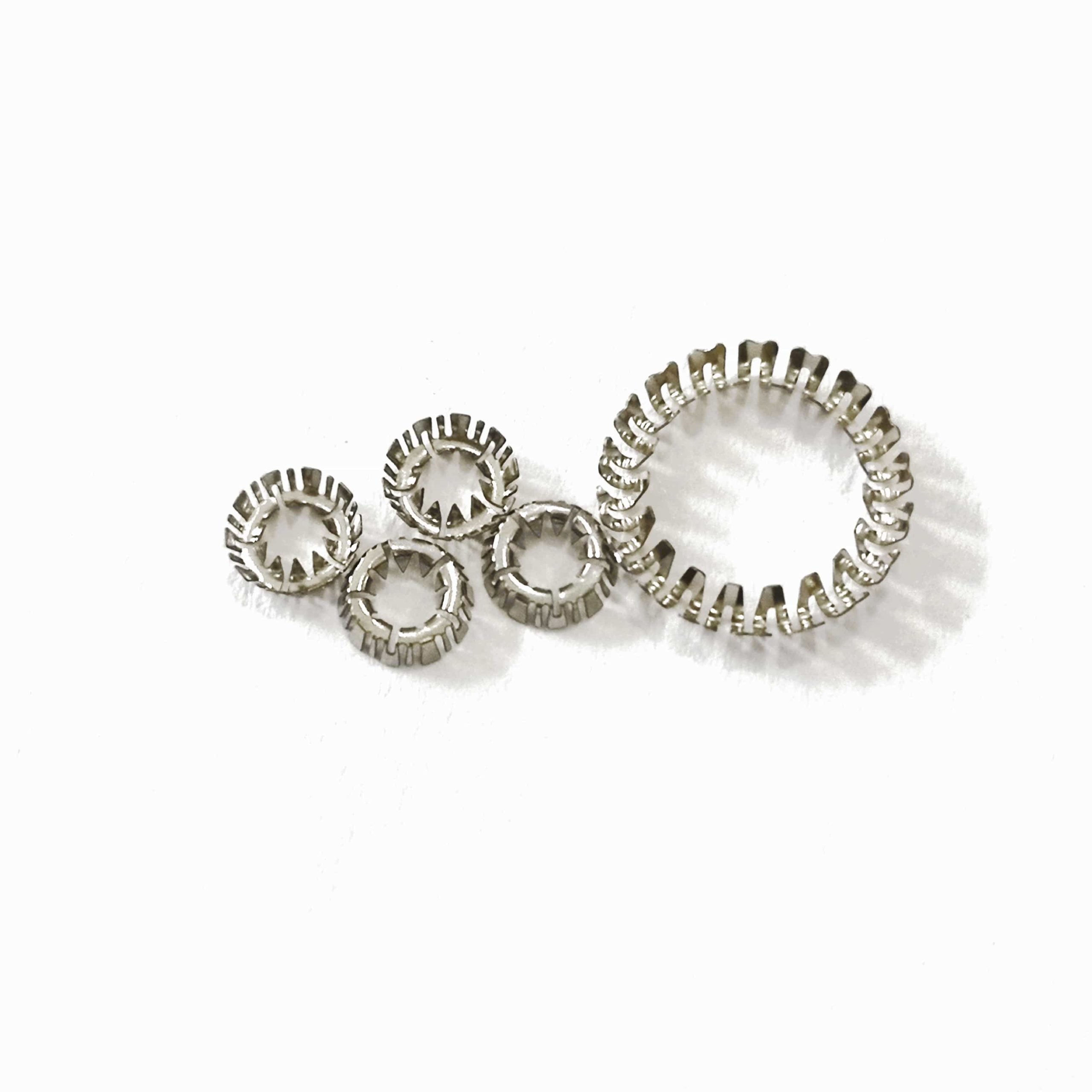
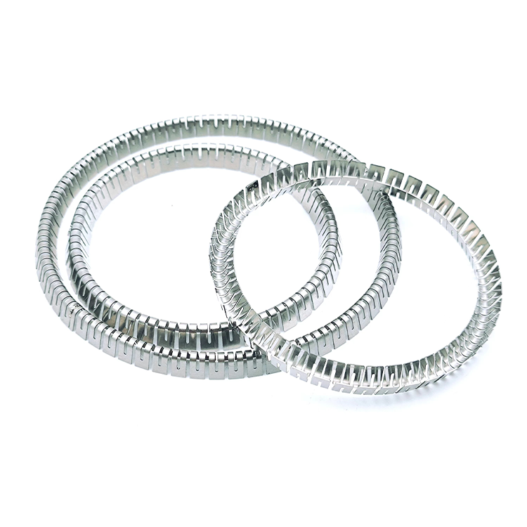
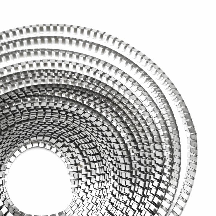
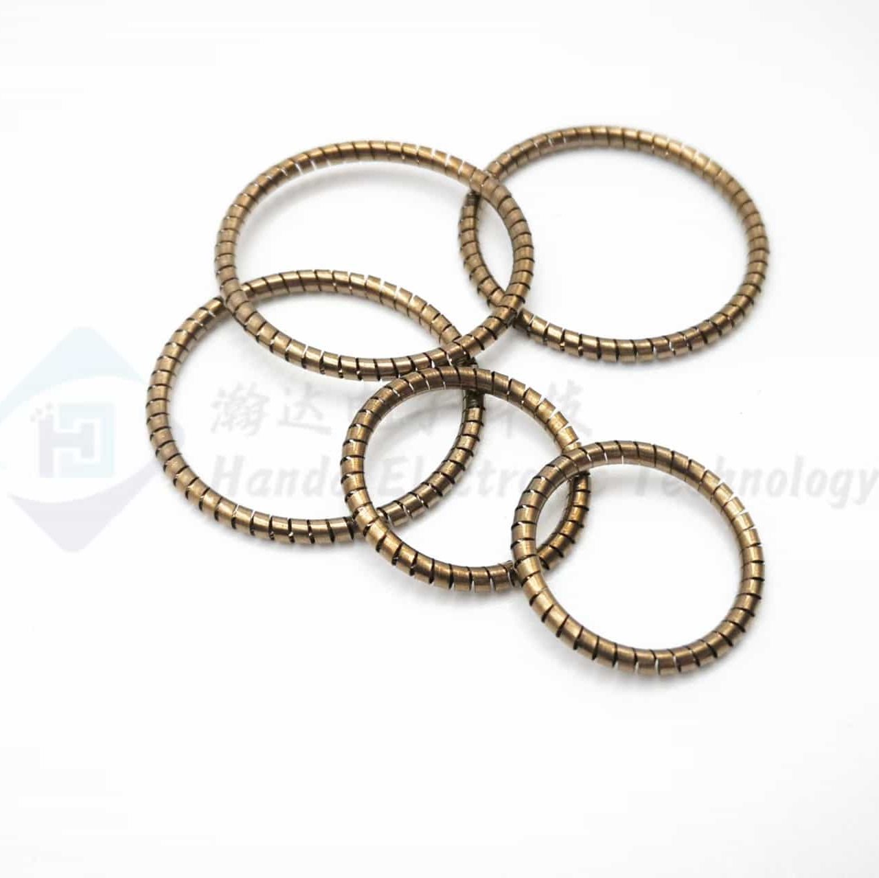
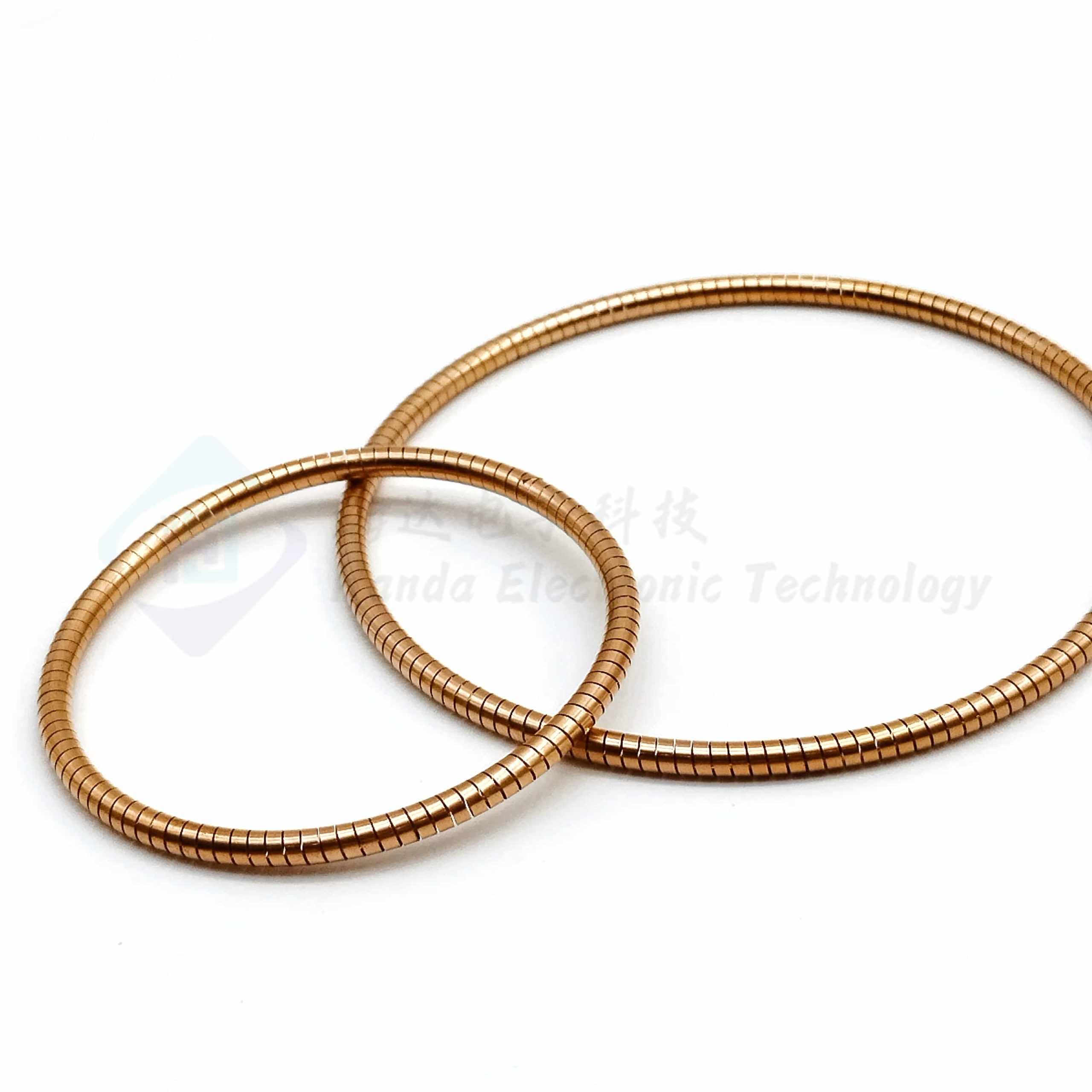
Our Canted Coil Springs are precision-engineered elastic sealing elements designed for high-pressure valves, hydrogen systems, aerospace fluid lines, chemical processing equipment, and critical sealing interfaces. With their unique slanted coil geometry, these springs deliver a highly stable, predictable load-deflection curve, ensuring consistent sealing performance even under extreme pressure, rapid pressure cycling, vibration, or thermal fluctuctuations.
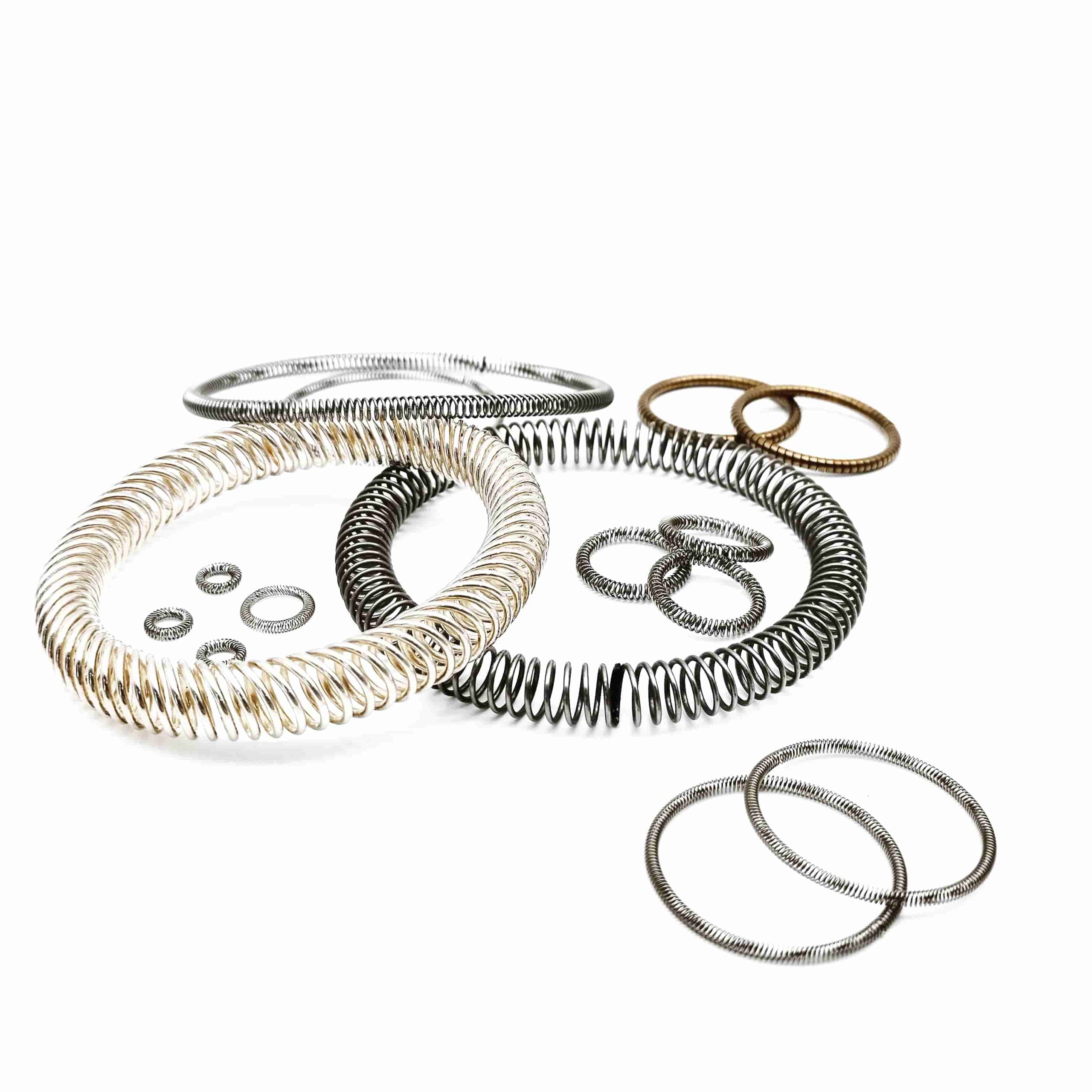
Manufactured with high-performance materials such as 17-7PH, MP35N, Inconel® X-750, or stainless steel, canted coil springs provide excellent corrosion resistance, low creep, and superior fatigue life, making them ideal for long-term, maintenance-free applications.
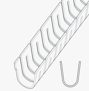
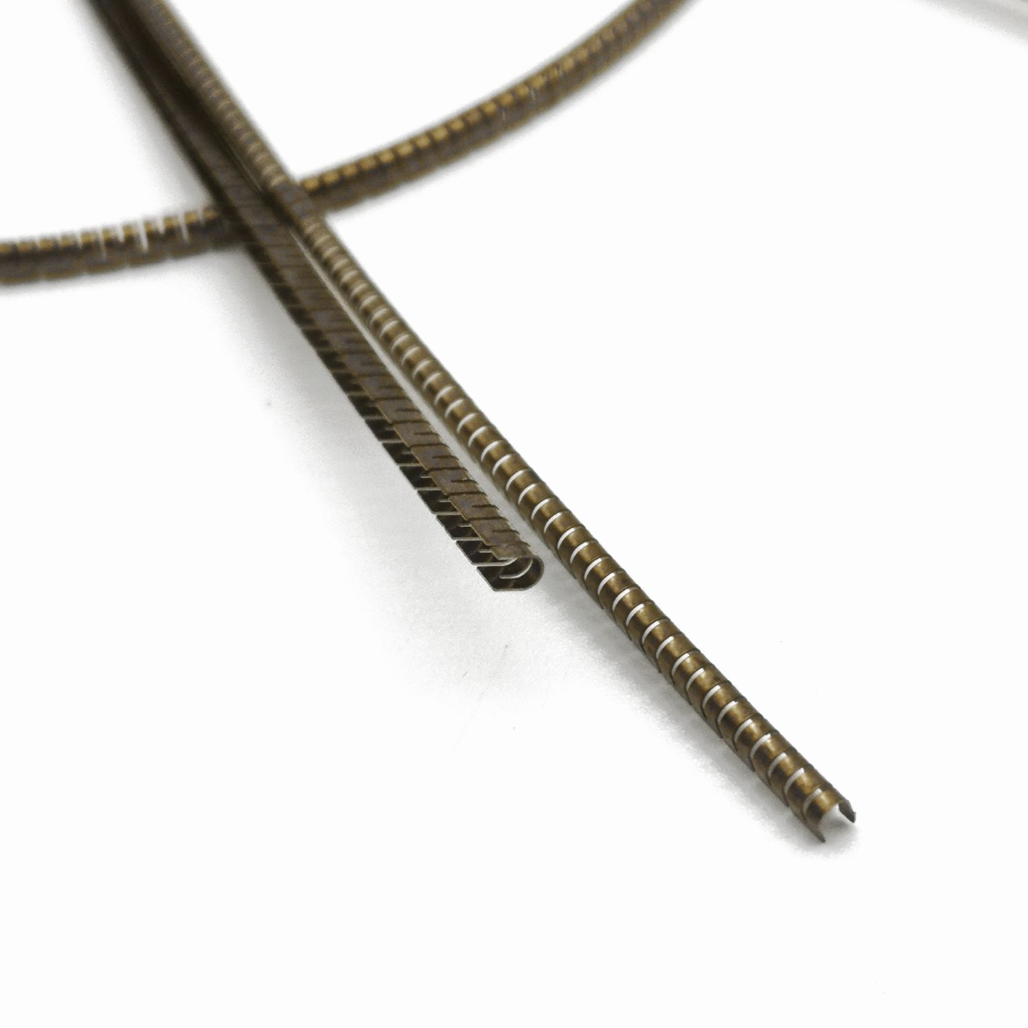
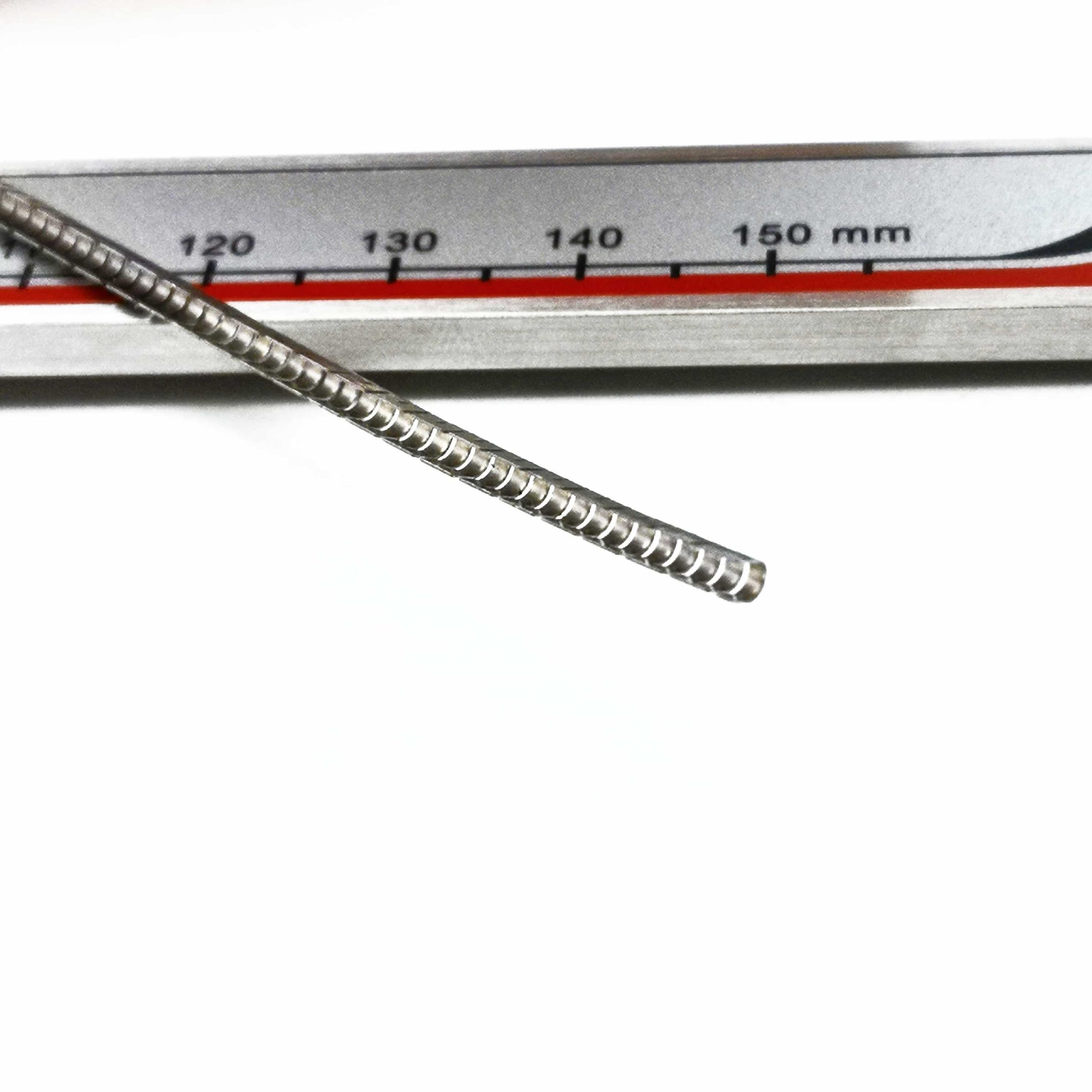
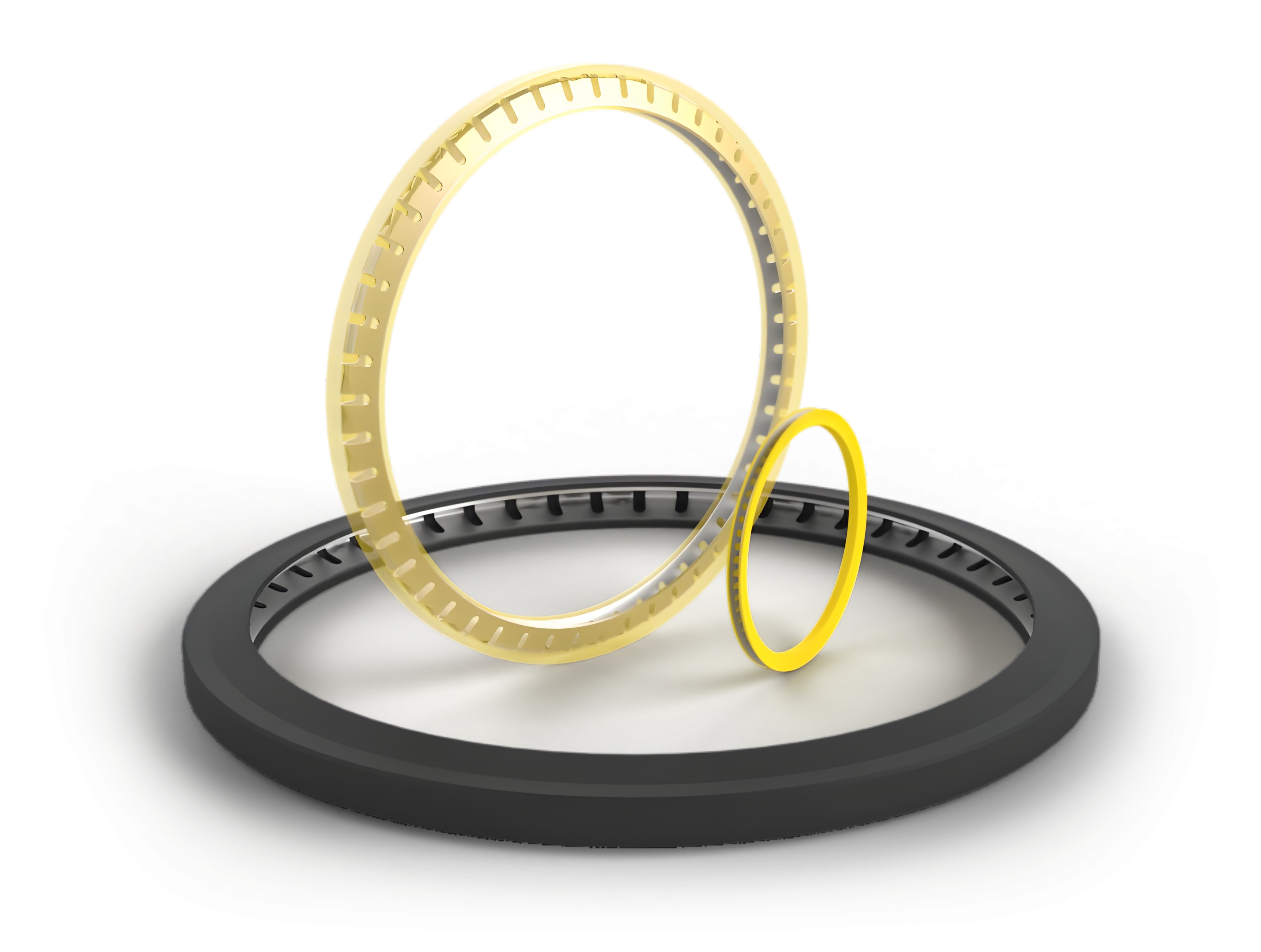
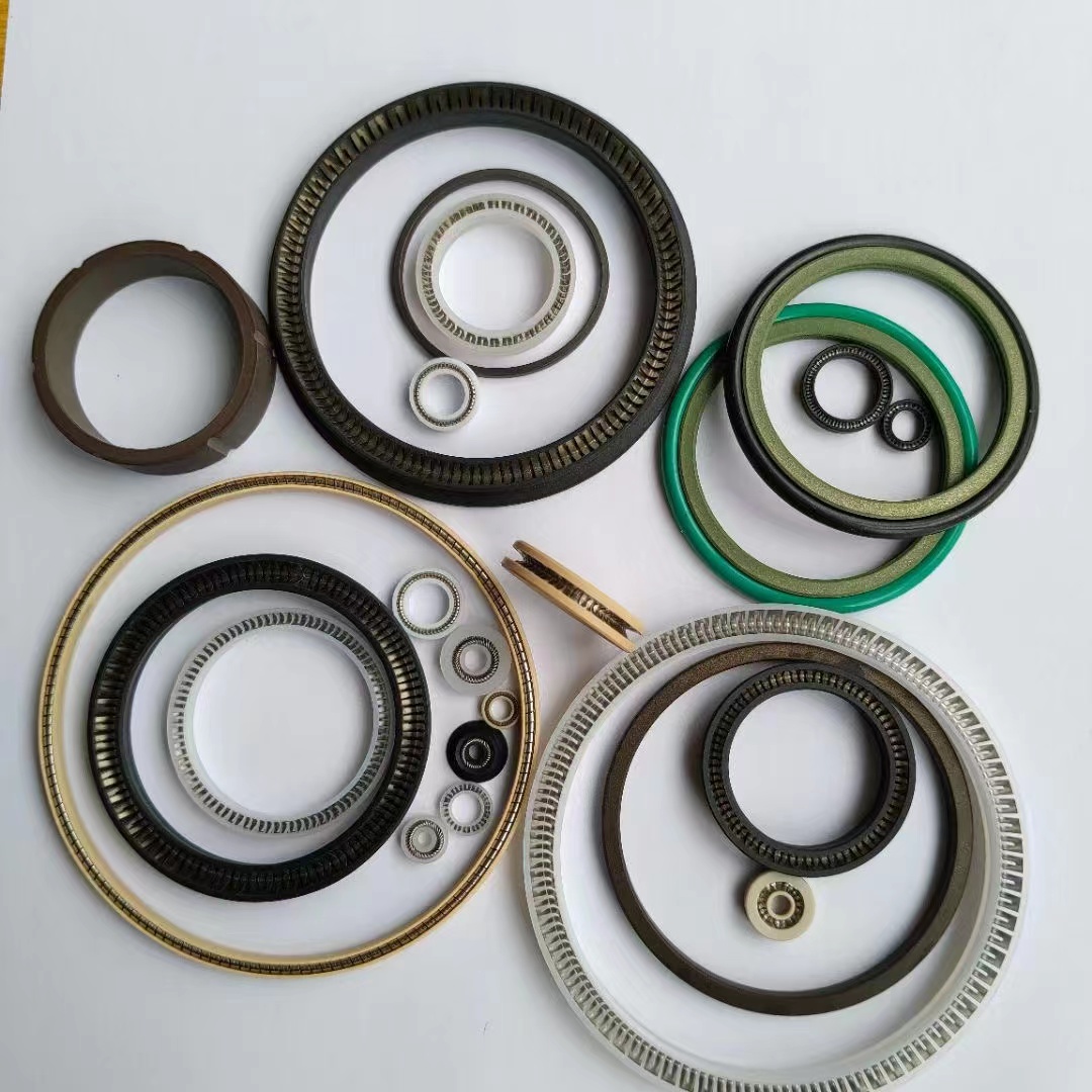
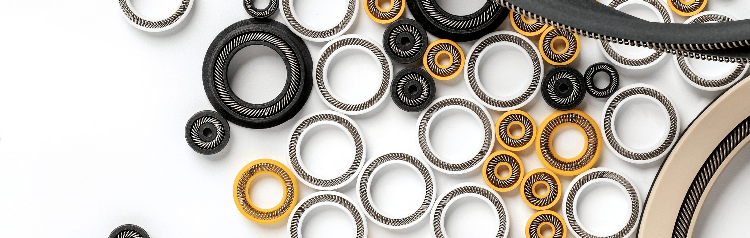
The spring can be integrated into U-cup seals, metal-to-metal seals, PTFE/PEEK energized seals, or customized sealing grooves in valves, compressors, and connectors. Through precise control of coil angle, wire diameter, free height, and spring force, our canted coil springs maintain consistent sealing force without risk of extrusion or permanent deformation, even in ultra-high-pressure environments.
Whether used for static sealing, dynamic reciprocating motion, or rotational sealing, canted coil springs ensure your system achieves leak-free reliability, extended service life, and enhanced safety performance.