
その理由 コイルスプリング 高圧バルブのシール不良を防ぐために、機械的な原因、設計上の誤り、材料要因、技術的な解決策を学びます。.
コイルばね、コイルばね押出成形、ばね通電押出成形、コイルばねシール、高圧バルブばね押出成形
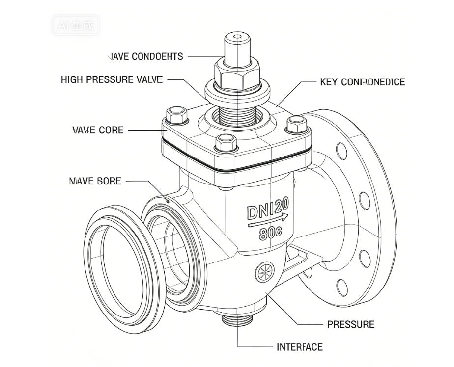
カンテッドコイルスプリングの押し出しは、高圧バルブの重大な故障モードです。 カンテ・コイル・スプリング 出物 大きな差圧がかかったり、形状がずれたりすると、溝から漏れることがある。この記事では、現象を説明し、典型的な故障シナリオとその結果(漏れ、シャットダウン、シールの故障)を示し、4つの工学的原因(力学、材料、溝設計、設置)を分析し、具体的な設計、材料選択、設置の解決策を示す。バルブとシールのエンジニアが押し出しを防止するのに役立つ図(力図、断面図、溝設計)と比較表が含まれています。.
定義 押出 この現象は、流体圧がかかると、カントコイルスプリング(スプリングエナジャイザー)が意図された溝/グランドから外れる不可逆的な移動または塑性変位を意味し、予圧が失われ、シールが破損する。.
カンテッドコイルスプリングエクストルージョンとは、流体圧力がかかった状態でスプリングが溝から外れる不可逆的な移動または塑性変位を指し、シールの不具合につながります。典型的なシナリオは、急速な圧力サイクルシステム、極低温または高温バルブ、タイトなグランド形状を持つシステムなどです。.
重大な影響には、即時の漏洩や格納容器の喪失、汚染を引き起こすポリマージャケットの破裂、緊急停止や予定外のメンテナンス、水素や酸素、化学物質を扱うようなセーフティ・クリティカルなシステムにおける致命的な故障などがある。.
主な機械的原因は、過剰な正味圧力と集中的なサイドロードで、流体圧力がスプリングの着座能力を超える力を発生させ、コイルの移動を引き起こします。加えて、過大なグランドクリアランス、温度や化学物質による材料の軟化、不適切な取り扱いや設置も主な原因です。.
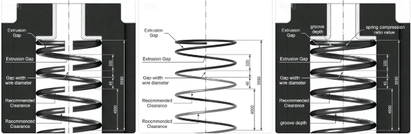
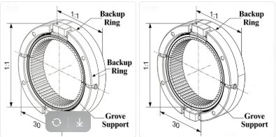
グランドクリアランスが大きすぎるとコイルが横方向に移動し、通電装置が不安定になる。推奨される設計ルールには、30MPa以上の圧力で半径方向のクリアランスを0.20mm以下に維持すること、溝の深さをスプリングの高さに合わせること、圧力進入面取りまたはバックアップリップを追加することなどがあります。.
インコネル718、エルジロイ、X-750のような材料は、降伏強度が高く、高温での安定性が高いため、標準的な302ステンレス鋼と比較して押出耐性を大幅に向上させることができるため、推奨される。.
典型的なシナリオ(押し出しがよく観察される):
深刻な結果だ:
以下では、その根本的な原因を分析する。 機械的, 材料そして デザイン ビューポイントこのセクションはエンジニアの技術的な核となる。.
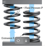
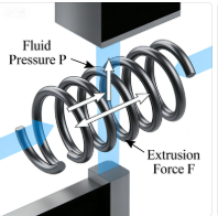
メカニック 流体圧力が露出した部分に作用すると、正味の軸方向/半径方向の力が発生し、スプリングの着座状態を維持する能力を超える可能性があります。簡単な関係:
Fp=P×A露出
押し出しが始まると いつ Fpに横方向の成分を加えたものが、スプリング-グランド・アセンブリの構造抵抗(ワイヤーの降伏と接触摩擦を含む)を超える。.
エンジニアリングの見識: 高い差圧+狭いサポートは、コイルの滑りとジッパーのような移動をもたらす。.
デザインの原因: ラジアルまたはラテラルクリアランスが推奨値より大きい場合、コイルがクリアランス内に横方向に移動する可能性があります。最初のコイルの動きは、通電装置全体を不安定にします。.
主要な幾何学的故障モード:
材料: 多くのステンレス鋼は、高温で降伏強度を失ったり、侵食性のある媒体によって脆化したりする。ジャケットとして使用されるポリマーはクリープすることがある。.
効果 低歩留まり→プラスチックが流れやすい→押出成形。ポリマーは負荷がかかると隙間にコールドフローすることがある。.
人間/組み立て要因: 不適切な配向、過度の伸張、表面損傷、潤滑不足は、コイル移行の原因となる局所的な応力集中を引き起こす可能性がある。.
以下にそれぞれの原因に対する具体的な対策を示す。チェックリストと比較表を使って、適切な方法を選びましょう。.
グルーブデザイン・クイックルール(推奨):
| 素材 | 標準的な収率(20) | 適した温度範囲 | 耐押し出し性(定性的) |
|---|---|---|---|
| 302 SS | ~500 MPa | -200~200°C | 低・中程度 |
| 17-7PH | ~1000 MPa | -200~250°C | グッド |
| インコネル718 | ~1250 MPa | -200~700°C | 素晴らしい |
| エルジロイ | ~1200 MPa | -200~600°C | 素晴らしい |
最も重要な選考基準:
日常的/業務的予防措置:
A.コストとパフォーマンスのトレードオフ - 高性能合金(インコネル、エルジロイ)は、材料費を上昇させるが、ダウンタイムと故障リスクを低減する。ライフサイクル・コスト・モデルを使って比較する。.
B.代替通電装置 - オールメタル Cリング、Eリング、またはセグメント化されたメタルシール ポリマークリープのリスクを取り除く。加工精度とコストのトレードオフを考慮する。.
C.耐押し出し性を検証するための試験方法 - 静水圧破裂試験、繰返し圧力試験、熱サイクル試験、FEA接触応力シミュレーション。.
予防 傾斜コイルスプリング 押出 高圧バルブには、正しい組み合わせが必要だ。 溝形状, 適切な バネの材質と形状, そして厳しい インストレーション・コントロール. .上記のチェックリストと図を使用して、設計を検証し、漏れのない長期的なバルブの動作を保証してください。.
より詳細なソリューションが欲しい、または任意の議論を必要とする、お気軽にお問い合わせください。.
Email:sale01@handaspring.com
この記事で提供されている技術情報、図解、テストデータ、図表、および技術的な例は、以下を目的としています。 一般的な参照のみ. .キャントコイルスプリングまたは高圧シールシステムの実際の性能、材料挙動、定格圧力、および設計要件は、以下の条件によって大きく異なる場合があります。 業界標準、アプリケーション環境、規制要件、顧客固有の設計仕様.
本記事で示した数値、計算式、試験結果、画像はすべて 例証的性質 そして 違う は、製品選択、エンジニアリング設計、または安全上重要な決定の唯一の根拠として使用することはできません。使用者は、常にデータを 適切な基準, 行動 第三者試験, そして、資格のある専門家に相談すること。 エンジニアまたは技術専門家 設計を実施したり、運用に使用する材料を選択したりする前に。.
出版社は、誤り、脱落、またはここに提供された情報の使用から生じるいかなる結果に対しても責任を負わない。.