
Discover why скошенная спиральная пружина extrude in high-pressure valves and learn the key mechanical causes, design mistakes, material factors, and engineering solutions to prevent sealing failure.
Canted coil spring,canted spring extrusion, spring energizer extrusion, canted coil spring seal, high-pressure valve spring extrusion
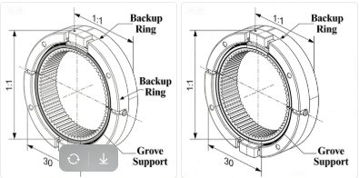
Canted Coil Spring Extrusion is a critical failure mode in high-pressure valves where the cante coil spring extrudes from its groove under large differential pressure or misfit geometry. This article explains the phenomenon, shows typical failure scenarios and consequences (leakage, shutdown, seal failure), analyzes four engineering causes (mechanics, materials, groove design, installation), and gives concrete design, material-selection, and installation solutions. Diagrams (force diagram, cross-section, groove design) and comparison tables are included to help valve and seal engineers prevent extrusion.
Definition: Extrusion here means the irreversible migration or plastic displacement of the canted coil springs (spring energizer) out of its intended groove/gland under applied fluid pressure, resulting in loss of preload and seal failure.
Canted Coil Spring Extrusion refers to the irreversible migration or plastic displacement of the spring out of its intended groove under applied fluid pressure, leading to seal failure. Typical scenarios include rapid pressure cycling systems, cryogenic or high-temperature valves, and systems with tight gland geometries.
The serious consequences include immediate leakage and loss of containment, rupture of polymer jackets causing contamination, emergency shutdowns and unplanned maintenance, and catastrophic failure in safety-critical systems such as those handling hydrogen, oxygen, or chemicals.
The primary mechanical cause is excessive net pressure and concentrated side-loads, where fluid pressure produces forces that can exceed the spring’s ability to remain seated, leading to coil migration. In addition, oversized gland clearances, material softening due to temperature or chemicals, and improper handling or installation are key causes.
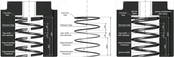
Oversized gland clearance allows the coils to laterally translate, destabilizing the energizer. Recommended design rules include maintaining radial clearance less than or equal to 0.20 mm for pressures above 30 MPa, matching groove depth to spring height, and adding a pressure-entry chamfer or backup lip.
Materials like Inconel 718, Elgiloy, or X-750 are recommended because of their high yield strength and stability at elevated temperatures, which significantly improve extrusion resistance compared to standard 302 stainless steel.
Typical scenarios (where extrusion is commonly observed):
Serious consequences:
Below we analyze the root causes from механический, материалы, и дизайн viewpoints. This section forms the technical core for engineers.
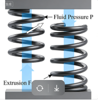
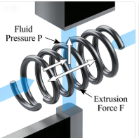
Механика: the fluid pressure acting over the exposed area produces a net axial/radial force that may exceed the spring’s ability to remain seated. Simplified relation:
Fp=P×Aexposed
When extrusion initiates: when Fp plus any lateral component exceeds the structural resistance of the spring–gland assembly (including wire yield and contact friction).
Engineering insight: high differential pressure + narrow support leads to coil glide and zipper-like migration.
Design cause: when radial or lateral clearances are larger than recommended, the coils can laterally translate into the clearance. First-coil movement destabilizes the whole energizer.
Key geometric failure modes:
Материалы: many stainless steels lose yield strength at elevated temperatures or are embrittled by aggressive media; polymers used as jackets can creep.
Effect: lower yield -> easy plastic flow -> extrusion. Polymers can cold-flow into gaps under load.
Human/assembly factor: incorrect orientation, overstretch, surface damage, or lack of lubrication can produce local stress concentrators causing coil migration.
Below are concrete countermeasures for each cause. Use the checklist and the comparison table to pick the right approach.
Groove design quick rules (recommended):
| Материал | Typical yield (20°C) | Suitable temp range | Extrusion resistance (qualitative) |
|---|---|---|---|
| 302 SS | ~500 MPa | −200 to 200°C | Low–Moderate |
| 17-7PH | ~1000 MPa | −200 to 250°C | Хорошо |
| Inconel 718 | ~1250 MPa | −200 to 700°C | Превосходно |
| Никель-молибденовые сплавы | ~1200 MPa | −200 to 600°C | Превосходно |
Most critical selection criteria:
Daily / operational preventive measures:
A. Cost vs performance trade-offs — High-performance alloys (Inconel, Elgiloy) raise material cost but reduce downtime and failure risk. Use a lifecycle cost model to compare.
B. Alternative energizers — All-metal C-rings, E-rings, or segmented metal seals remove polymer creep risk. Consider trade-offs: machining precision and higher cost.
C. Test methods to validate extrusion resistance — hydrostatic burst, cyclic pressure testing, thermal cycling, and FEA contact-stress simulations.
Preventing Уплотнения со скошенными спиральными пружинами Extrusion in high-pressure valves requires combining correct groove geometry, adequate spring material and geometry, and strict installation controls. Use the checklists and diagrams above to validate your design and ensure long-term, leak-free valve operation.
Want more detailed solutions or you need any discuss,please feel free to contact us.
Email:sale01@handaspring.com
The technical information, illustrations, test data, diagrams, and engineering examples provided in this article are for general reference only. Actual performance, material behavior, pressure ratings, and design requirements for canted coil springs or high-pressure sealing systems may vary significantly depending on industry standards, application environments, regulatory requirements, and specific customer design specifications.
All numerical values, formulas, test results, and images shown in this article are illustrative in nature and should not be used as the sole basis for product selection, engineering design, or safety-critical decisions. Users should always verify data against the appropriate standards, conduct independent testing, and consult with qualified engineers or technical specialists before implementing any design or selecting materials for operational use.
The publisher assumes no responsibility for errors, omissions, or any consequences arising from the use of the information provided herein.